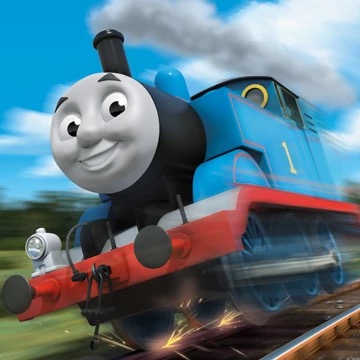
DCC is control through the rails. A small decoder inside each locomotive listens for its own address.
Workshop guide · checked 23 July 2026
Make your Thomas locomotive digital
Look at the product number first. Then choose the simple Next18 route or the careful soldering route for an older model.
Bachmannofficial manuals
NMRAwiring standard
Digitrax + TCSinstallation guidance
Step 1 · check first
Check your locomotive
Choose a model or enter the product number found under the locomotive or on its box.
Yes — Thomas 58741 is DCC-ready
You need a Next18 decoder. No soldering is required.
No confirmed Next18 match for
View the 5 stepsFind the correct manual
This number is not in the confirmed list. Check the exact model and its own manual before choosing a decoder or opening the locomotive.
✓Green: confirmed Next18 model?Not in this confirmed list: check the exact model
DCC-ready is not DCC-fitted. “Ready” means there is a socket; the decoder is normally sold separately.
New decoders start at address 3. Test that address on a programming track before changing anything.
← Check another model
✓ DCC-ready · no soldering
Thomas 58741
Fit Next18 in 5 clear steps
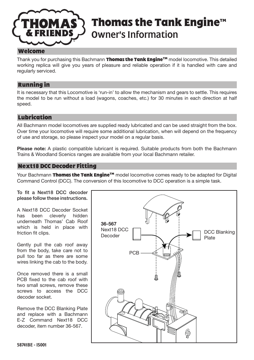
Use a Next18 decoder (NEM 662). Bachmann’s current recommendation is 36-567A, which replaces 36-567 and 36-567B.
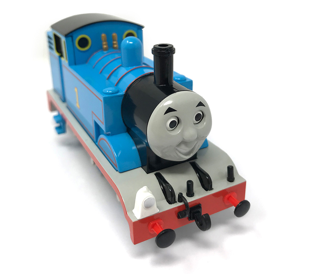 Thomas58741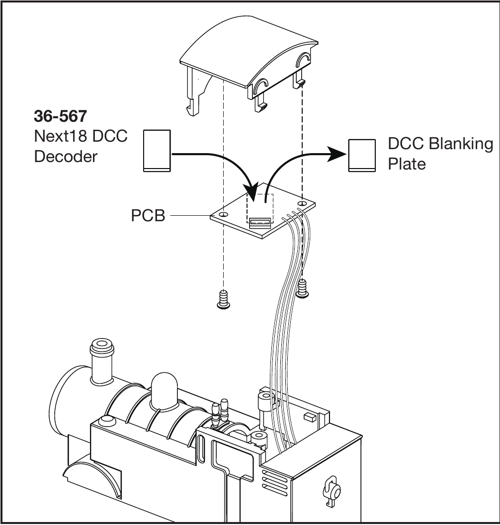
Open this modelLift the friction-fit cab roof carefully. Do not pull it far: wires connect the roof PCB to the body.
- 01Switch everything off
Remove the locomotive from the track. Work on a soft, clean cloth and keep every screw grouped.
- 02Open only as shown
Follow the selected Bachmann manual. Faces, eye mechanisms and wires are delicate.
- 03Remove the blanking plate
Pull the small factory plug straight out of the Next18 socket. Never twist the pins.
- 04Press in the decoder
Align the contacts and press the Next18 decoder squarely into place. Do not force it.
- 05Test before closing
Put the model on a programming track, read or test address 3, then refit the body without trapping wires.
Do not use a generic 8-pin decoder. These nine current European models use the much smaller Next18 connector. Check the code, not only the character.
Find the correct manual
Check the product number on the box or locomotive and compare the manual for that exact version. A missing match does not establish which decoder connection is fitted. Leave the locomotive disconnected until the connection is confirmed.
Ask us to identify your model
Route 02 · older DC-only models
Hardwiring a confirmed DC-only model
A basic motor-only decoder needs two rail inputs and two motor outputs. The motor must be electrically isolated from both rails and the metal chassis.
Test motor isolation before connecting track power.
With a multimeter, neither motor terminal may have continuity to either rail pickup or any metal chassis part. If it does, stop and isolate it. An unisolated motor can destroy the decoder immediately.
STOPContinuity found? Do not switch on.
Wiring diagramFour wires. Two clear functions.
Rails feed the decoder. The decoder alone feeds the isolated motor.
Rails
BLACKLeft rail
REDRight rail
DCCdecoder
GRAYmotor output
ORANGEmotor output
Misolated motor✓ Fully isolated
Photograph and trace
Test the locomotive on DC first. Photograph every connection. Identify the two rail pickups and the two motor terminals by function.
Remove the direct DC path
Disconnect both motor terminals from rail pickups, PCB traces and any chassis contact. Preserve suppression parts only when the decoder maker instructs you to.
Prove isolation
Use continuity or resistance mode: motor terminal to left rail, right rail and chassis. Repeat for the other terminal. Every test must be open circuit.
Solder by function
Black + red go to the two rail pickups. Gray + orange go only to the isolated motor. Use short stripped ends, electronics solder and heat-shrink.
Inspect, program, close
Insulate every joint, secure the decoder away from gears and moving eyes, test on the programming track at address 3, then refit the shell.
Do not match the locomotive’s old wires by colour.
The decoder colours above are standardised; wiring inside an older model may not be. Trace and test each connection. Function beats colour.
What you actually need
Put these five essentials within reach before you begin.
-
Next18 decoder
A decoder small enough to fit and rated above the locomotive’s measured stall current
-
Multimeter
A multimeter with continuity and resistance modes
-
Fine soldering iron
A fine electronics soldering iron, electronics solder and flux
-
Wire & insulation
Fine wire, strippers, tweezers, heat-shrink and Kapton tape
-
Soft bench + instructions
A soft work mat, small screw trays and the exact model instructions
Three quick answers
The details that prevent most mistakes.
Does DCC-ready mean a decoder is already fitted?
No. It means a socket is present. The model normally runs on analogue DC through a blanking plate until you install a decoder.
The locomotive runs backwards. Is it wired wrong?
For a hardwired model, first recheck isolation and connections. If everything is safe, swap orange and gray at the motor or change the decoder’s direction setting—never swap only one rail wire.
What about lights and sound?
This page shows only the four-wire motor circuit. Lights need function outputs and suitable resistors; sound also needs speaker space and a sound project. Follow that decoder’s own manual.
Sources & safety notes
Last checked: 23 July 2026. Always let the manual for your exact product number override a general guide.
The older-model route also uses the supplied Silver Band tutorial transcript as a practical starting point. Its four motor/rail wires are retained here, but the instructions are corrected to require motor isolation and function tracing before soldering. Product photos and manual illustrations belong to Bachmann. Work on an unpowered model and stop if the exact wiring is uncertain.
Ready for your next model?
Browse Bachmann Thomas locomotives, rolling stock and model railway sets.